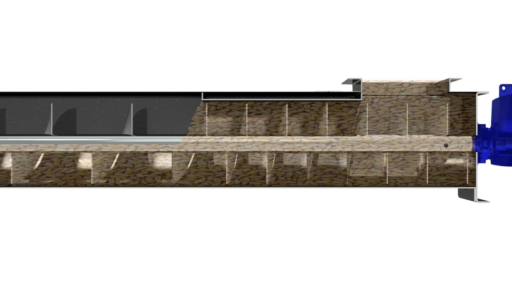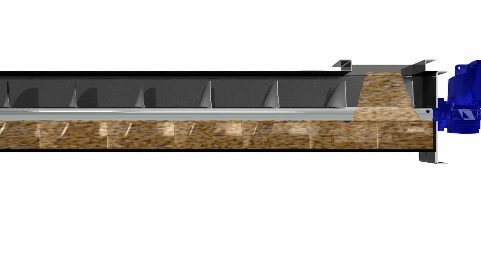
A screw feeder is defined as a screw conveyor with a flooded inlet where it is expected to output a constant flow rate at the discharge. Screw feeders can be designed to fit a range of applications and configurations. Once the critical question of, “Is it a conveyor or feeder?” is answered the next information needed is similar to that of a screw conveyor. The bulk material being fed, bulk density, required flow rate, inlet size and material height above the inlet are all needed to properly design a screw feeder. The focus of this article is on the physical size of the screw feeder in reference to diameter and flight pitch. A future article will focus on sizing the drive for RPM and HP.
We can break the screw feeder design down into a couple of broad categories, a simple screw feeder and a mass flow screw feeder. The difference is dependent on the ratio of the length to width of the inlet and discussed below.
Simple Screw Feeder
A simple screw feeder has a length to width ratio of the inlet less than 2:1, meaning the inlet is the width of the trough and no more than 2x for the length. These types of feeders are typically under a small hopper like a bulk bag unloader, day use bin or some other similar storage bin. Some of the key elements of the design are below
Reduced flight pitch through the inlet. The pitch of the flight is critical to control the flow rate along with the screw RPM. For this type of screw feeder, a single section of reduced pitch through the inlet allows the flighting to open up after the shroud and give the bulk material room to breath and expand after being compressed in the hopper and through the shroud.
Feeder shroud after the inlet. The feeder shroud should be at least 2x the screw feeder diameter, meaning a 9in feeder would have an 18in long shroud. This is sufficient distance to keep the bulk material at the inlet from forcing its way through the screw in most cases. The main exceptions being very fine powders like carbon black or cement which can fluidize and require a special shroud to prevent bulk material bypass.
Mass Flow Screw Feeder
Mass flow is a term used lightly, but in this case refers to a screw feeder with a length to width ratio of the inlet more than 2:1, meaning the inlet is the width of the trough and more than 2x for the length. These types of feeders are under larger bins and silos where the capacity required does not allow the material to funnel to a single, small discharge. Some of the key elements of the design are below
Flight pitch through the inlet. The main design differences between these two types of screw feeders are in the design of the screw through the inlet. While a simple screw feeder can get away with a single pitch through the inlet a mass flow screw feeder cannot. A single pitch through a long inlet would only draw bulk material from the very end and then try and drag in under the rest of the inlet compressing the bulk material, possible clogging the inlet or causing a bridge in the hopper. Instead, mass flow screw feeder uses either multiple pitch changes, a cone screw or a tapered screw to ensure proper flow. A future article will focus more on mass flow screw feeder design but for the purpose of this article it is important to know special consideration should be taken in the screw design for this type of screw feeder.
Screw Feeder Size
There are a few basic formals and rules of thumb needed to size a screw feeder. The first is the required flow rate and the bulk density of the material. The biggest question asked about a screw feeder is what speed should I run? The best rule of thumb is to run your screw feeder 20-40rpm. Above 40 rpm can reduce torque and make it hard for the screw feeder to start up. Below 20 RPM will provide plenty of torque but maybe so much it makes the shafts too large to be practical. In some true mass flow feeder designs under large silos the screw feeder will run at 5rpm or slower to allow the bulk material to evenly discharge but those are rare, very highly engineered solutions.
Screw Feeder Example:
Required Flow Rate: 10,000 pounds per hour
Bulk Material: Corn meal
Bulk Density: 32-40 pounds per cubic foot
Assumptions:
Let’s start with a 9″ screw feeder with a half (4.5″) pitch through the inlet and feeder shroud.
Assume a 2″ dia drive shaft and a 2 ½” (2.875″ OD) center screw shaft
For the sizing calculation we want to calculate the worst-case scenario, meaning using the lightest bulk density (32pcf) with the highest required flow rate (10,000pph)
The inlet is a standard 1:1 ratio, meaning the width is the same as the inlet.
Calculation:
Do – Outer Diameter = 9″
Di – Inner Diameter = 2.875″
P – Pitch = 4.5″
PPH – Required Flow Rate = 10,000 pounds per hour
D – Density = 32
% – % fill level of the screw – 100%
RPM – Revolutions per minute
Screw Conveyor Speed in RPM:
Speed=(6912* PPH)/(188.5*%*P*D*(Do^2-Di^2))
Speed=35 RPM
For additional help sizing your screw feeder, contact us and one of our screw conveyor experts will be happy to help out.

Simple Screw Feeder with Flooded 1:1 Inlet

