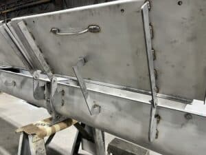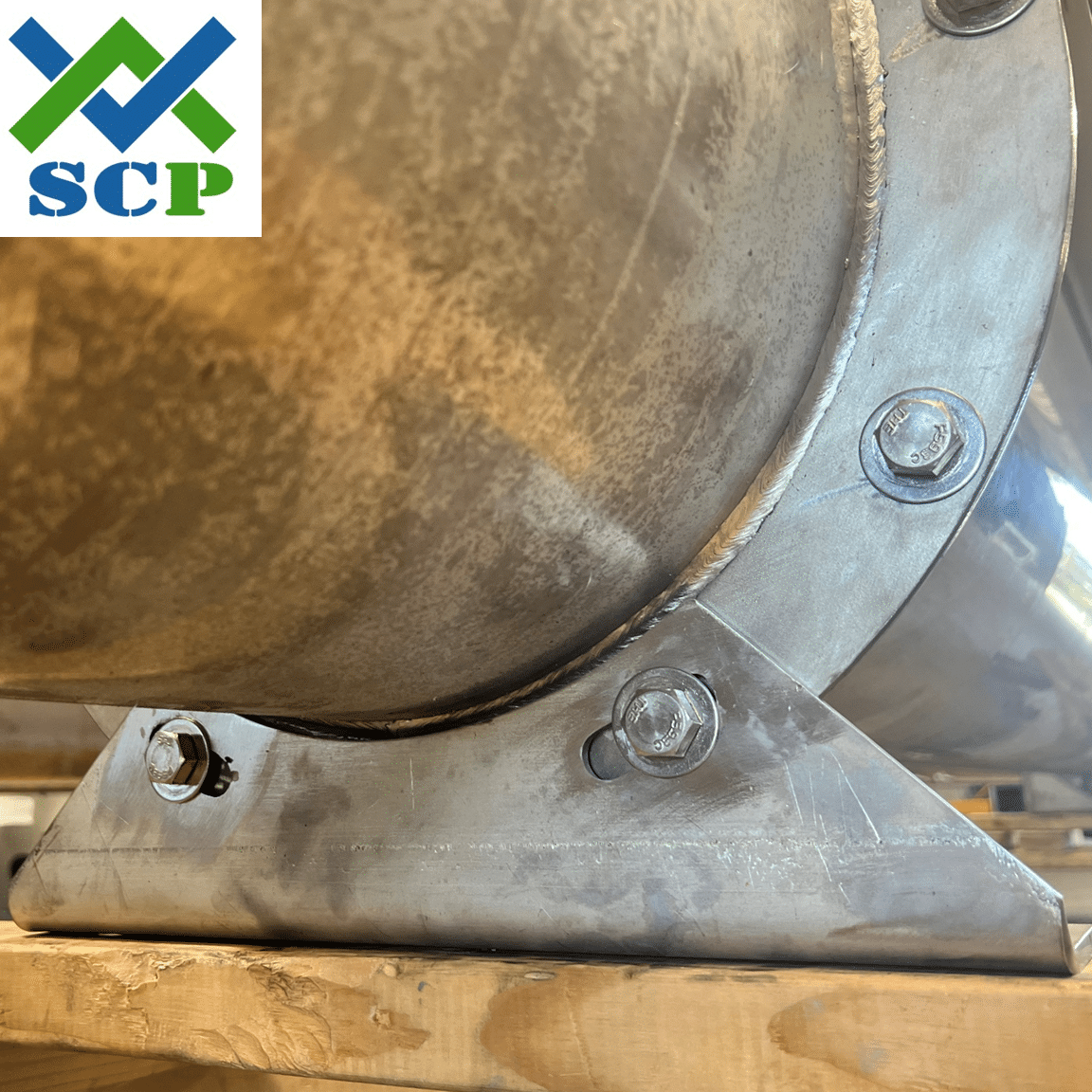
Screw conveyors can be configured to fit a lot of different applications and layouts. Many times, how to support the screw conveyor becomes a challenge for plant designers due to the unique support requirements of a screw conveyor and compact and complicated plant layouts. To allow more flexibility for the designer, screw conveyors can be fitted with both feet and saddles to allow for greater flexibility. The foot is supplied at every trough joint, while the saddle can be fitted anywhere along the trough.
In general, screw conveyors need to be supported at each end and no more than every 10ft (for 6” and 9”) and 12ft (For 12” and up) between the ends, which also corresponds with the standard trough lengths of screw conveyors. At the ends, the troughs ends are designed with feet to allow for mounting. Standard practice is to supply a foot at each trough joint, which naturally accounts for the required support spacing described above. It is not recommended to use the inlet or discharge as support points since they are attached to relatively week sections of troughs, when compared to the trough ends or trough flanges.

Foot
The screw conveyor foot is designed to attach at the trough flanges and is held in place with the trough end flange bolts. The foot has mounting slots on the bottom to allow for bolting to the required support. The drop of the foot from the centerline of the screw conveyor is the same as the trough ends so the supports can all be built at the same level.

Saddle
The screw conveyor saddle is designed to be attached (welded) to the trough at any point along the trough. The saddle has a reinforcing mounting pad to distribute the load on the trough and reduce the chance of bending or denting the trough with mounting slots on the bottom to allow for bolting to the required support. The drop of the saddle from the centerline of the screw conveyor is the same as the trough ends so the supports can all be built at the same level.

