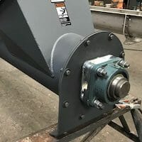
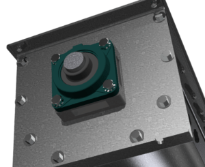
The trough ends are located at the ends of the screw conveyor and used to enclose the trough, or housing. The trough end plays a vital role in the successful operation of the screw conveyor. In addition to containing the material in the trough, the trough end has to support the weight of the screw through the use of the end bearing and allow for mounting of the shaft seal used to keep material from coming out of the trough at the drive or tail shaft penetrations.
As many know and many others do not, the trough end bolting and sizing are standardized by CEMA’s standard number 300; screw conveyor dimensional standards. These standards ensure all the CEMA member company are building screw conveyor components to the same dimensions, including the trough ends. This standard number 300 provides common overall dimensions, thickness and bolting patterns.
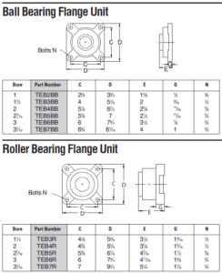
So with all this said about standards, where can one go wrong with a trough end? The answer is in the selection of the flange bearing attached to the trough end. CEMA standard number 300 does standardize the bolting patterns for different types of flange bearings sizes 1 ½” – 3 7/16″. The key to success is making sure the correct flange bearing bolt pattern is selected for your trough end. A 2″ dia flange roller bearing has a substantially different bolting pattern than a 2″ flange ball bearing. As a reminder, you typically want a roller bearing on the drive end and a ball bearing on the tail end to allow for and run out in the tail shaft. Using a screw conveyor drive can help mitigate this possible mix-up because the screw conveyor drives are usually designed in a way to bolt to a wide variety of trough end bearing bolting patterns.
The chart below shows the various CEMA flange bearing bolting patterns for both roller and ball bearings.
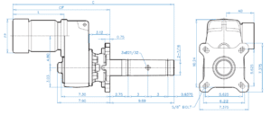
The image below shows the large slots used by drive manufacturers to accommodate various trough end bolting patterns.
A Note about Manufacturers
Some manufacturers have helped with this problem by designing the trough end bolting pattern to accept both ball and roller bearings of each size. Easily enough, the 3″ ball and roller flange bearings use the same pattern. The 2″ is substantially different and no one makes a universal pattern for it. It is still a good idea to specify your bearing type when ordering to avoid having to grind out the bearing mounting holes at assembly.
A Note about Pillowblock Bearings
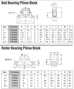
Pillowblock bearings are used to remotely locate bearings away from the screw conveyor trough end and are very useful when a shaft seal upgrade is required or the bearing needs to be isolated from high temperature. The same problem or bolt patterns exists for screw conveyor trough ends, also called pedestal trough ends, designed for pillowblock bearings.
The chart below shows the various CEMA pillowblock bearing bolting patterns for both roller and ball bearings.
A Note about 3 15/16″ and up Shaft
CEMA has created dimensional standards for shaft sizes 3 15/16″ and 4 7/16″, but to our knowledge no screw conveyor manufacturer has implemented them yet, so you will need to specify the bearing manufacturer and type when ordering these shaft sizes. Larger shaft sizes will also require this information to be correctly manufactured.

